
Belt Conveyor Training Course: Basic Components and Operation Guide
- What is a belt conveyor?
- Part One: Key Features of Belt Conveyors
- Part Two: Working Principle of Belt Conveyors
- Part Three: Frame
- Part Four: Conveyor Belts
- Part Five: Idlers
- Part Six: Drive Unit
- Part Seven: Rollers
- Part Eight: Braking Systems
- Part Nine: Hydrodynamic Coupling
- Part Ten: Tensioning Device
- Part Eleven: Cleaning Device
- Data sources:
What is a belt conveyor?
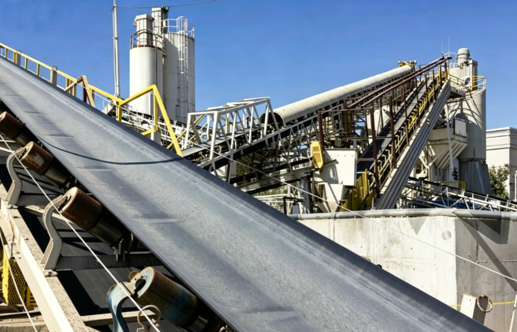
A belt conveyor is a piece of machinery that utilises the principle of friction drive to transport materials continuously. It can transport materials continuously from a starting point to a destination along a fixed conveyor line. Belt conveyors are capable of transporting both bulk materials (such as coal, ore and grain) and packaged goods (such as cartons and bagged goods). They can also be integrated with factory production processes to form rhythmic assembly lines. Consequently, belt conveyors are widely used in various industrial enterprises.
In power stations, the vast majority employ high-efficiency fixed belt conveyors, which are used in conjunction with stacker-reclaimers.
A belt conveyor primarily consists of the following components:
Drive unit
Idlers
Frame
Scraper
Tensioning device
Braking system
Part One: Key Features of Belt Conveyors
Reliable operation
The primary advantage of belt conveyors is their reliable operation. They can operate continuously and stably over long periods with a low failure rate.
Low power consumption
As there is virtually no relative movement between the material and the conveyor belt, the operating resistance of belt conveyors is minimal, amounting to approximately one-third to one-fifth that of scraper conveyors. At the same time, wear and breakage of the material during transport is minimal, resulting in high productivity. These characteristics all contribute to reducing production costs.
Flexible Conveying Routes
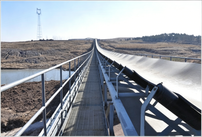
The conveying routes of belt conveyors can be flexibly designed as required, ranging from a few metres to over 10 kilometres in length. They can be installed within small tunnels or erected above ground in areas with heavy traffic or hazardous conditions.
Multi-point loading and unloading
Depending on process requirements, belt conveyors can very flexibly receive material from a single or multiple points, and can also unload to multiple points or sections. For example, in a coal preparation plant beneath a coal silo, when multiple feeders simultaneously feed material onto a single conveyor belt, that belt becomes the main conveying trunk line.
Material Retrieval and Mixing Functions
Belt conveyors can retrieve material from tunnels beneath stockpiles in coal yards and, where required, mix materials from different stockpiles. Material can be discharged simply at the head of the conveyor, or at any point along the length of the belt using a plough-type unloader or a mobile unloading vehicle.
Excellent overall performance
The conveyor belt serves both as the load-bearing component and the traction element that transmits tensile force. It is driven by the friction between the belt and the rollers. Belt conveyors offer the following advantages:
High conveying capacity
Excellent climbing ability
Simple structure
High adaptability to various materials
High production efficiency
Smooth and reliable operation
Continuous and uniform material conveyance
Low operating costs
Easy maintenance
Suitable for automatic control and remote operation
Good environmental performance
Belt conveyors operate with low noise levels. Where necessary, the conveyor belt can be enclosed within a housing to prevent dust from dispersing and polluting the air. At transfer stations, dust can be contained within chutes; if connected to a dust collector, dust particles can also be captured.
Part Two: Working Principle of Belt Conveyors
The working process of a belt conveyor is as follows:
The conveyor belt is guided around the drive drum and the tail return drum, forming a closed loop. The upper and lower sections of the belt are supported by idler rollers. A tensioning device provides the tension required for normal operation.
During operation, the drive pulley propels the conveyor belt through friction between the pulley and the belt. Material (such as coal) is placed on the conveyor belt and moves along with it.
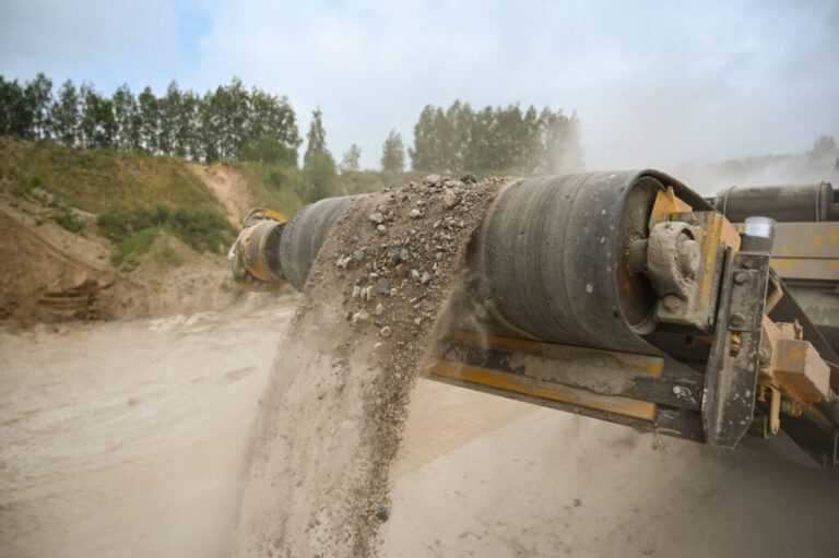
Belt conveyors typically transport material via the upper section of the belt and unload it at the end. Specialised unloading devices can also be used to unload material at any desired location.
Part Three: Frame
Types of Frame
Belt conveyors have two types of frame structure: floor-mounted and suspended. Floor-mounted frames are further divided into fixed and mobile types. Coal preparation plants primarily use fixed floor-mounted frames.
Components of the Frame
The frame of a fixed belt conveyor is a structural assembly welded from angle steel and channel steel. Depending on their purpose, frames can be classified as:
| Frame Type | Application |
|---|---|
| Head frame | Mounts the drive pulley and bend pulley |
| Tail frame | Mounts the tail pulley |
| Intermediate frame | Mounts the carrying idlers and return idlers |
| Drive unit frame | Mounts the drive unit |
Specifications of the intermediate frame
The intermediate frame is assembled from individual sections and is available in both standard and non-standard specifications:
| Type | Length |
|---|---|
| Standard intermediate frame | 6000 mm |
| Non-standard intermediate frame | 3000 – 6000 mm |
The two ends of the centre frame are connected to the head frame and tail frame. The width of the centre frame is approximately 300–500 mm greater than that of the conveyor belt. The height of the centre frame is generally 550–650 mm.
Part Four: Conveyor Belts
Types of Conveyor Belts
There are two types of conveyor belts used in general-purpose belt conveyors: rubber belts and plastic belts.
Operating temperature range of conveyor belts
| Conveyor Belt Type | Ambient Temperature | Material Temperature Limit |
|---|---|---|
| Standard Rubber Belt | -10°C to +40°C | Not exceeding +50°C |
| Fire-Resistant Conveyor Belt | — | Use when material exceeds +90°C |
| Cold-Resistant Conveyor Belt | -50°C to -15°C | — |
When the temperature exceeds 50°C, the elasticity of the belt begins to decline; when the temperature is too low, the belt becomes stiff and cracks may appear.
The importance of conveyor belts
Conveyor belts are the most expensive and least durable components of a belt conveyor. During operation, conveyor belts are subjected to loads of various types and are under complex stress conditions.
The most common forms of damage to conveyor belts include:
Wear on the working surface and edges
Punctures, tears and delamination caused by impacts from large pieces of material
Fatigue resulting from repeated bending of the core
Ageing and reduced strength caused by environmental factors
Empirical data: Conveyor belts account for approximately half of the total equipment cost of a conveyor system.
Therefore, selecting the appropriate conveyor belt based on operating conditions and strengthening maintenance management during operation are of great significance for improving conveyor efficiency and reducing production costs.
Classification of cover rubber
| Cover Grade | Cut Resistance | Tear Resistance | Abrasion Resistance | Oil Resistance | Application |
|---|---|---|---|---|---|
| Grade I | Excellent | Excellent | Excellent | Not recommended | Conveying large lump ores and sharp, cutting materials under extremely severe working conditions |
| Grade II | Good | Excellent | Excellent | Not recommended | Conveying abrasive screened materials with low cutting effect under heavy working conditions |
Class I conveyor belts: The cover rubber is made from natural rubber, synthetic rubber or a mixture of both, with the aim of achieving the best overall resistance to cutting and abrasion.
Class II conveyor belts: The cover rubber offers good abrasion resistance, but its resistance to cutting and chipping is inferior to that of Class I belts.
Core strength
| Conveyor Belt Type | Strength |
|---|---|
| Standard Rubber Belt (fabric ply) | 560 N/cm·ply |
| Multi-ply Plastic Belt (fabric ply) | 560 N/cm·ply |
| Solid Woven Belt (4mm thick) | 2240 N/cm·ply |
| Solid Woven Belt (5mm thick) | 3360 N/cm·ply |
Classification by Core Material:
By core fabric:
Cotton canvas core
Nylon-polyester fabric core
Polyester fabric core
Steel cord core
By cover rubber properties:
Standard type
Heat-resistant type
Cold-resistant type
Part Five: Idlers
Classification of Idlers
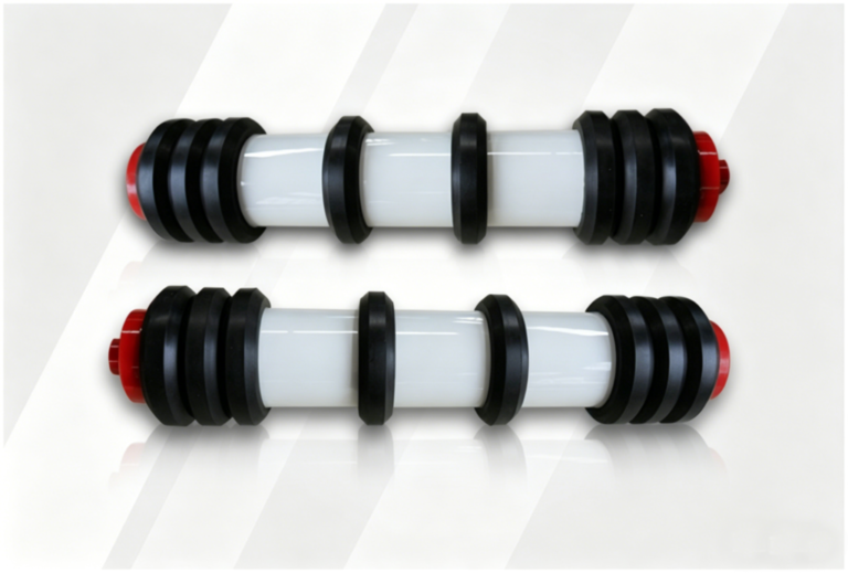
Idlers are classified into two types: steel idlers and plastic idlers. Steel idlers are mostly made from seamless steel tubes.
Relationship between Idler Diameter and Belt Width
| Belt Width B (mm) | Idler Diameter (mm) |
|---|---|
| ≤ 800 | φ89 |
| 1000 – 1400 | φ108 |
Reference: Standard Design for General-Purpose Fixed Conveyors
Classification of idlers by application
| Idler Type | Function |
|---|---|
| Trough idler | Supports the loaded belt (carrying side / upper run) on the carrying side (upper run) for bulk material |
| Flat (parallel) idler | Supports the empty belt on the return side (lower run) |
| Impact idler | Reduces material impact on the belt at the loading point |
| Self-aligning idler | Prevents and corrects belt misalignment (belt running off‑center) |
Trough idlers
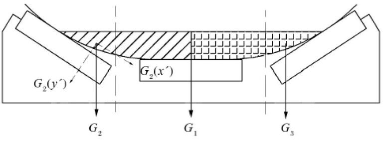
Trough idlers generally consist of three short idlers. The angle between the axis of the inclined idler and that of the horizontal idler is known as the trough angle. The trough angle is a key parameter in determining conveying capacity.
| Trough Angle | Description |
|---|---|
| 20° | Commonly used in the past |
| 30° | Adopted in the TD75 series design |
| 35°, 45° | Also commonly used today |
Empirical data: Under identical belt width conditions, increasing the trough angle from 20° to 30° increases the cross-sectional area for conveying bulk materials by 20% and boosts throughput by 13%, whilst simultaneously reducing material spillage.
Buffer idlers
The function of buffer idlers is to reduce the impact of material on the belt at the discharge point, thereby protecting the conveyor belt. Buffer idlers are classified as:
Rubber ring-type buffer idlers (rubber rings fitted over the tube body)
Spring plate-type buffer idlers (with elastic supports)
Spring plate-type rubber ring buffer idlers
Self-aligning idlers
To prevent and correct belt misalignment:
In heavy-load sections: Install one set of trough-type self-aligning idlers for every 10 sets of trough idlers
In return sections: Install one set of lower flat-type self-aligning idlers for every 6 to 10 sets of lower idlers
Principle of operation: When the conveyor belt deviates, the edge of the belt presses against the vertical roller, causing the idler frame to rotate through a certain angle about the vertical axis. This generates a tangential velocity opposite to the direction of deviation, pulling the conveyor belt back to the centre position. Once the belt returns to the centre, the idler frame also returns to its normal position.
Specialised idlers
Spiral idlers: Non-stick and highly self-cleaning, these resolve issues such as material adhesion, belt deviation and tearing, whilst automatically correcting deviation to prevent the conveyor belt from being torn by twisted material.
Comb-type idlers: Used to clear material adhering to the surface of the conveyor belt.
Ceramic rollers: With excellent wear resistance, suitable for harsh operating conditions.
Part Six: Drive Unit
Components of the drive unit
The drive unit is the power source of the belt conveyor and generally consists of the following components:
Motor
Hydraulic coupling
Gearbox
Coupling
Drum
Braking system (backstop)
The motor drives the drive drum via the hydraulic coupling and gearbox; the conveyor belt is propelled by the friction between the drum and the belt.
Drive configurations
Depending on the operating conditions and requirements, drive configurations can be categorised as follows:
Single-motor drive / Multi-motor drive
Single-drum drive / Twin-drum drive / Multi-drum drive
Motor
Y-series motors are commonly used in belt conveyors. In areas where there is a risk of coal dust explosions, explosion-proof motors must be used.
Gearbox
The gearbox is the speed-reducing mechanism between the motor and the drive drum, serving to reduce rotational speed and increase torque. Cylindrical gearboxes are commonly used in belt conveyors, offering advantages such as compact design, high efficiency, reliable operation, long service life and low maintenance requirements.
Coupling
The connection between the motor and the gearbox, and between the gearbox and the drive drum, is achieved by means of a coupling.
| Coupling Type | Features | Applicable Applications |
|---|---|---|
| Nylon pin coupling | Compact size, light weight, simple structure, reliable operation | General applications |
| Fluid coupling (hydraulic coupling) | Balances motor load, dampens shock and vibration | Long-distance, heavy-duty conveyors |
Part Seven: Rollers
Classification of rollers
Rollers are classified into two types: drive rollers and deflection rollers.
| Pulley Type | Function |
|---|---|
| Drive pulley | Drives the conveyor belt through friction between the pulley surface and the belt, while also changing the belt direction |
| Bend / deflector pulley | Only changes the direction of the belt; does not transmit power (e.g., tail pulley, vertical take‑up pulley) |
Drum surface types
| Surface Type | Applicable Conditions |
|---|---|
| Smooth steel pulley | Low power, low ambient humidity |
| Rubber‑lagged pulley | Humid environment, high power, prone to slippage |
Rubber-coated drums offer the advantages of high friction and resistance to coal adhesion. The surface patterns available include:
| Pattern Type | Features | Applicable Applications |
|---|---|---|
| Chevron (herringbone) | High friction coefficient, good water drainage, directional | For one‑way (unidirectional) belt travel; the chevron pattern must be oriented in the belt running direction during installation |
| Diamond | — | For reversible (bidirectional) conveyors |
Methods of drum manufacture
Welded drums: Steel plates are rolled and then butt-welded
Cast drums: Manufactured by casting
Rubber-coated drums: Featuring a thick rubber surface, high wear resistance and excellent quality, they are widely used
Enveloping angle and traction
To transmit sufficient traction, there must be adequate friction between the conveyor belt and the drum. According to the theory of friction transmission, greater traction can be achieved by increasing the coefficient of friction or by increasing the enveloping angle.
| Drive Arrangement | Wrap Angle |
|---|---|
| Single‑pulley drive | 180° – 240° |
| Dual‑pulley (tandem) drive | 360° – 480° |
A twin-drum drive significantly increases the conveyor’s traction, making it particularly suitable for long-distance conveying.
Part Eight: Braking Systems
When are braking systems required?
When belt conveyors are used for inclined material transport, back-up devices or braking systems should be installed where the average gradient exceeds 4° to prevent the conveyor from reversing or slipping when stopped under full load.
Common back-up and braking systems
There are three main types in standard designs:
| Type | Description |
|---|---|
| Belt backstop | Suitable for small incline angles and low power |
| Roller backstop (overrunning clutch type) | Suitable for medium incline angles and medium power |
| Hydraulic electromagnetic shoe brake | Suitable for large incline angles and high power |
Part Nine: Hydrodynamic Coupling
Principle of Operation of a Hydrodynamic Coupling
A hydrodynamic coupling consists of main components such as the drive shaft, pump impeller, turbine, driven shaft and rotating casing. The pump impeller and turbine are arranged symmetrically, have identical geometric dimensions, and are fitted with radially radiating vanes.
During operation, the coupling is filled with working fluid (DTE Light). When the drive shaft rotates the pump wheel:
Under the action of centrifugal force, the working fluid flows from the inner side of the pump wheel towards the outer edge, forming a high-pressure, high-speed fluid flow.
This high-pressure, high-speed fluid flow impacts the turbine blades, causing the turbine to rotate in the same direction as the pump wheel.
Within the turbine, the working fluid flows from the outer edge towards the centre, where its pressure decreases and velocity slows down;
The working fluid then returns to the pump wheel inlet, forming a continuous cycle;
During this process, the pump wheel converts the mechanical energy from the input shaft into the kinetic and potential energy of the working fluid, whilst the turbine converts the kinetic and potential energy of the working fluid back into mechanical energy at the output shaft, thereby achieving power transmission.
Advantages of the hydraulic coupling:
Smooth start-up under load, improving start-up performance
Provides overload protection
Isolates torsional vibration impacts
Balances motor loads in multi-motor drive systems
Reduces inrush current in the power grid
High efficiency and simple structure
Maintenance-free operation
Part Ten: Tensioning Device
The function of the tensioning device
The function of the tensioning device is:
To ensure the conveyor belt has sufficient tension, thereby generating the required friction between the drum and the belt
To limit the sag of the conveyor belt between the idler rollers
To ensure the normal operation of the conveyor
Selecting a suitable tensioning device and determining a reasonable installation position are essential conditions for ensuring that the conveyor belt does not slip on the drive drum.
Types and Comparison of Tensioning Devices
| Type | Working Principle | Advantages | Disadvantages | Applicable Conditions |
|---|---|---|---|---|
| Screw take-up | Rotating screw to move the pulley | Simple and compact structure | Tension cannot be kept constant | Conveyor length < 80m, low power |
| Gravity winch take-up (carriage type) | Gravity of counterweight pulls the carriage via wire rope | Automatic tensioning, constant tension | Requires large space at tail end | Long distance, high power, especially suitable for inclined conveyors |
| Vertical gravity take-up | Gravity of counterweight moves the pulley up and down along guide rails | Automatic tensioning, constant tension | Many bend pulleys; material may fall between belt and take-up pulley | Conveyor length > 100m, limited space at tail end |
| Hydraulic take-up | Hydraulic power unit + tension buffer + automatic control | Adjustable tension, automatic control, absorbs tension fluctuations | Complex structure, high cost | Long distance, high power, high automation requirements |
Screw tensioning
The bearing housings at both ends of the tensioning drum are mounted on a slide block fitted with a nut; the slide block can move along the tail frame. Turning the screw causes the drum to move forwards or backwards. The thread must be self-locking to prevent loosening.
Counterweight Trolley Tensioning
The tail tensioning drum is mounted on a trolley that can move along the tail frame guide rails. One end of the wire rope is connected to the trolley, whilst the other end suspends a counterweight. The conveyor belt is tensioned by the weight of the counterweight, allowing for automatic tensioning and maintaining a constant tension.
Vertical Counterweight Tensioning
The drum is mounted on a frame, with the counterweight suspended from the frame; the frame moves up and down along guide rails. Suitable for conveyors of considerable length (>100 m) or where end-of-line space is limited, it is typically installed near the drive drum or utilises the space beneath a walkway.
Hydraulic Tensioning Device
Components:
Base
Hydraulic Power Unit
Recoiling Winch
Tension buffer device
Control box
Tension sensor
Automatic control workflow:
The operator presses the start button, and the system enters operational mode
The control system performs a self-check on the belt tension
If the check is normal, the hydraulic power unit is activated
A solenoid valve controls the oil supply to the tension buffer device
When the wire rope tension reaches the set upper limit, the oil supply is stopped
The control cabinet sends a start signal, and the conveyor starts and accelerates.
Once steady-state operation is achieved, the controller relieves pressure from the tension buffer to reduce tension.
When tension drops to the normal operating value, the tension buffer self-locks to maintain tension.
The hydraulic station ceases operation.
Tension Monitoring: The tension sensor and control cabinet automatically monitor the tension. Should the tension be detected as less than 0.95 times the set lower limit, the system automatically reactivates the tensioning mechanism to increase the tension to the set lower limit.
Buffering function: The tension buffer cylinder and accumulator absorb brief fluctuations in tension during conveyor belt operation.
Manual mode: The winch’s forward and reverse rotation, the hydraulic power unit’s start/stop, and the buffer cylinder’s operation can be controlled individually. The winch is used solely to provide pre-tensioning during installation and commissioning and does not participate in the automatic tensioning process.
Part Eleven: Cleaning Device
Function of the cleaning device
During operation of the belt conveyor, fine coal particles adhere to the conveyor belt, causing it to run off-centre and increasing operational resistance. Consequently, belt conveyors are generally equipped with a cleaning device.
Types of cleaners
| Type | Description |
|---|---|
| Spring scraper | Uses spring pressure to press the scraper blade against the belt, scraping off coal adhering to the belt surface. The scraper blade is made of improved alloy steel. Scraped coal falls into the head chute. |
| Empty return scraper | Installed in front of the tail pulley, vertical take-up unit, and mid-drive unit. Removes adhered material from the non-carrying side of the belt. |
| P-type / H-type secondary head scraper | This type of scraper is commonly used for cleaning the carrying side of the belt conveyor. |
Data sources:
Design Standards for the TD75 Series Belt Conveyors (Standardised products of the former Ministry of Metallurgical Industry)
GB/T 10595-2017 ‘Belt Conveyors’
GB/T 7984-2013 ‘General-purpose Fabric-cord Conveyor Belts’
The correspondence between idler diameter and belt width in this document refers to the standard design for general-purpose fixed conveyors
Data on the relationship between trough angle and conveying capacity is referenced from the TD75 series design manual
Conveyor belt core strength data is referenced from GB/T 7984-2013 and industry design manuals
The operating principle of the hydraulic coupling is referenced from general industry technical documentation
Classification and parameters of tensioning devices are referenced from the ‘Code for Engineering Design of Belt Conveyors’ and industry design manuals

 English
 العربية
 Русский
 Español
 Português do Brasil