
Belt Conveyor Design: Practical Calculation & Selection Tips
- What is a belt conveyor?
- Part 1: Basic Components and Applications
- Part 2: Conveyor Belt Types and Applications
- Part 3: Basic Calculations: Load, Tension and Power
- Part 4: The CEMA Tension Theory Calculation Framework
- Part 5: Demonstration of Calculation Examples
- Part 6: Trough Belt Capacity, Belt Width and Belt Speed
- Part 7: Idlers and CEMA Classification
- Part 8: Drums, Tensioning and Drive
- Part 9: Material Impact, Cleaners and Accessories
- Part 10: Design Verification Checklist
- Conclusion: Summary and Standards Sources
- Source of data
What is a belt conveyor?
Belt conveyors are among the most common and cost-effective pieces of equipment used for the continuous conveyance of bulk materials. They are suitable for a wide range of applications, including mining, ports, cement production, power generation, chemical processing, grain handling, warehousing and manufacturing. Designing a belt conveyor involves more than simply selecting a belt and a motor. Engineers must carry out comprehensive calculations and verifications based on material characteristics, conveying capacity, belt speed, belt width, trough angle, idlers, drums, tensioning methods, power requirements and various accessories.
Part 1: Basic Components and Applications
1.1 Main Components
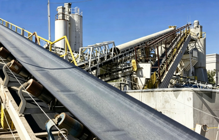
A belt conveyor typically consists of the following components: two or more drums, a continuous looped conveyor belt, load-bearing idlers, return idlers, a drive unit, a tensioning device, loading points, unloading points, and cleaning and protective accessories.
1.2 Working Principle
The upper surface of the conveyor belt is used to carry the material, whilst the lower surface runs unloaded during the return section. The drive drum propels the conveyor belt via friction, thereby enabling continuous material conveyance.
1.3 Applications
It is particularly well-suited for continuous conveyance over long distances, at high speeds, with high throughput, or where there is a significant elevation difference. Under suitable operating conditions, large-scale belt conveyors can significantly reduce operating costs compared to lorry transport.
1.4 Design Considerations
Key design considerations include: material characteristics, belt width and speed, tension distribution, power requirements, idler spacing, drum diameter, loading impact, and cleaning and maintenance.
Part 2: Conveyor Belt Types and Applications
The choice of conveyor belt cover rubber, reinforcement material and structural configuration must be based on material temperature, abrasiveness, oil and grease content, flame retardancy, impact resistance, incline angle and maintenance conditions. Common types are shown in the table below:
| Type | Key Features | Typical Applications |
|---|---|---|
| Standard rubber belt | Natural and synthetic rubber cover; suitable for most abrasive materials | General bulk material conveying |
| Cut-resistant belt | High natural rubber content; stronger resistance to cutting and gouging | Sharp, lumpy materials |
| Heat-resistant / ultra heat-resistant belt | SBR or chlorobutyl rubber cover | Clinker, hot ore, and other high-temperature materials |
| Flame-resistant belt | Chlorobutyl rubber cover with multi-layer carcass; meets underground safety requirements | Coal mining, underground conveying |
| Oil-resistant belt | Nitrile, chlorobutyl, or synthetic rubber cover; easy to clean | Materials containing vegetable or mineral oils |
| Steel cord belt | High strength, impact resistant; suitable for long-distance, high-tension conveying | Ports, mines, power plants, cement plants |
| Corrugated sidewall belt | Enables steep-angle lifting in small spaces without multiple transfers | Cement, chemical, port lifting conveying |
Part 3: Basic Calculations: Load, Tension and Power
3.1 Calculation of Load per Unit Length
The first step in the design process is to convert the conveying capacity (tonnes per hour) into the mass of material per metre of conveyor belt.
Empirical formula:
Q = 0.278 × Qt / v (kg/m)
Parameter explanation: Q = load per unit length, Qt = conveying capacity (tonnes/hour), v = belt speed (metres/second)
For example, for a conveyor with a conveying capacity of 400 tonnes/hour and a belt speed of 1.4 metres/second, Q = 0.278 × 400 / 1.4 ≈ 79.4 kg/m.
3.2 Components of Tension and Power
Effective tension (Te) is the total force required to drive the conveyor belt; it consists of several component forces:
Empirical formula:
Te = Tx + Ty + Tz + Tus
Where:
Tx: Tension required for running the empty belt
Ty: Tension required for horizontal movement of the material
Tz: Tension required to lift or lower the material
Tus: Resistance caused by friction between the material and the skirt board
Conveyors operating over short distances require a higher proportion of power to overcome friction; therefore, a length correction is necessary.
Empirical formula: Metric Lc = L + 70 metres
Parameter description: Lc = corrected length, L = actual horizontal length
Part 4: The CEMA Tension Theory Calculation Framework
The CEMA (Conveyor Equipment Manufacturers Association) method is a widely used system for calculating tension. It takes into account roller resistance, flexural resistance of the belt and material, skirt friction, lift height and additional resistance.
The formula for calculating drive power is as follows:
Empirical formula:
Metric: Power (CV) = Te (kg) × v (m/s) / 75
Imperial: Power (HP) = Te (lb) × v (ft/min) / 33,000
Data reference: CEMA ‘Belt Conveyors for Bulk Materials’
Part 5: Demonstration of Calculation Examples
Assume we need to design a belt conveyor with the following parameters: belt width 900 mm, horizontal length 250 m, head height 20 m, conveying capacity 400 tonnes/hour, belt speed 1.4 m/s, and the material being conveyed is coal.
Calculations based on the above formula yield the following key results:
| Parameter | Metric Result | Description |
|---|---|---|
| Unit load (Q) | 79.4 kg/m | Calculated from capacity and belt speed |
| Effective tension (Te) | 2775 kg | Includes empty belt, horizontal load, lift, and skirtboard resistance |
| Anti-slip tension (Tm) | 1054 kg | Assumes 210° wrap angle, rubber-lagged pulley, gravity take-up |
| Sag tension (Ts) | 684 kg | Based on 2% sag and idler spacing |
| Maximum working tension (T1) | 4051 kg | Used for belt strength and drive power verification |
| Drive power | Approx. 75 CV (approx. 100 kW) | Next standard motor power rating is recommended |
Part 6: Trough Belt Capacity, Belt Width and Belt Speed
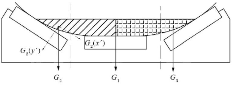
The greater the trough angle of the trough idlers, the larger the theoretical loading cross-sectional area and the greater the conveying capacity. However, a larger trough angle also places higher demands on the lateral flexibility of the conveyor belt.
Empirical formula:
Metric: Conveying capacity Qt = 3.6 × cross-sectional area × material density × v (tonnes/hour)
Data reference: CEMA ‘Belt Conveyors for Bulk Materials’
Part 7: Idlers and CEMA Classification
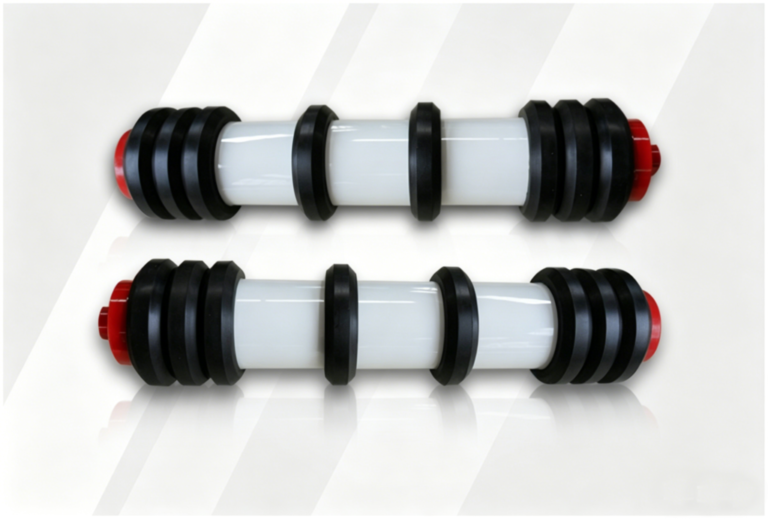
Idlers are key components that influence conveyor efficiency, belt life and operational stability. They account for a significant proportion of equipment costs, and their quality directly determines the reliability of the entire machine.
Trough idlers: Used for the ‘upper branch’ that carries the material.
Return idlers: Used for the ‘lower branch’ of the conveyor belt’s return run.
Impact Idlers: Positioned at loading points to absorb the impact of falling material; their spacing is typically half that of standard idlers.
Self-aligning Idlers: Used to correct belt misalignment; it is recommended to install one set approximately every 15 metres on the load side and every 30 metres on the return side.
Part 8: Drums, Tensioning and Drive
Drums are key components for power transmission, with common diameters ranging from 200 mm to 1600 mm.
Empirical formula (minimum drum diameter):
Dp > K × i
Parameter explanation: Dp = drum diameter (mm), K = coefficient (typically 125–150, depending on the number of belt plies), i = number of belt plies
For example, for a 6-ply canvas conveyor belt, the minimum drum diameter should be 125 × 6 = 750 mm.
Drive rollers are typically rubber-coated to increase the coefficient of friction; the coating thickness is commonly 6–12 mm.
Part 9: Material Impact, Cleaners and Accessories
The feeding system should minimise the drop height of the material to prevent large, sharp pieces from striking the belt directly. Buffer idlers or buffer beds are usually installed in the discharge area.
Static scrapers: These feature a simple design, using segmented blades to directly remove adhered material from the belt surface.
Dynamic scrapers: Driven by an electric motor, these involve higher capital and commissioning costs but are suitable for more complex cleaning scenarios.
Part 10: Design Verification Checklist
The following are recommended steps for preliminary design:
Confirm material properties: bulk density, maximum particle size, abrasiveness, temperature, moisture content, angle of repose and operating angle of repose.
Confirm operating conditions: conveying capacity, horizontal distance, lift height, incline angle, belt speed, operating time, start-up frequency and environmental conditions.
Preliminary selection of belt width and trough angle: estimate using the cross-sectional area and capacity formulae, allowing for sufficient margins.
Calculate tension: Break down by empty belt, load, lift, skirting, scrapers and additional equipment.
Verify drive: Slip conditions, wrap angle, drum lining, tensioning method and motor power.
Verify belt: Maximum tension, tension per unit width, number of plies or wire rope strength, troughing capability and minimum drum diameter.
Idler Arrangement: Load side, return side, loading zone, self-aligning idlers and transition section spacing.
Accessories: Hoppers, chutes, scrapers, enclosures, anti-drift, anti-blockage, dust control and maintenance access.
Conclusion: Summary and Standards Sources
The design of a belt conveyor is a systematic engineering process. The introduction and calculation formulas provided in this article can serve as a valuable reference for preliminary design. However, when undertaking formal engineering design, it is essential to integrate local project regulations, CEMA standards, equipment manufacturers’ product catalogues, and the client’s technical specifications.
| Standard / Reference | Purpose |
|---|---|
| CEMA Belt Conveyors for Bulk Materials | Provides calculations, capacity, tension, idler, and design guidelines for bulk material belt conveyors |
| ISO 5048 | Calculates operating power and tensile forces for belt conveyors with idlers |
| ISO 3684 | Determines minimum pulley diameters for conveyor belts |
| ISO 14890 | Specification for general-purpose fabric-core rubber or plastic covered conveyor belts |
| Dunlop Belt Design Manual | Reference for belt design, selection, and application |
Source of data
- CEMA (Conveyor Equipment Manufacturers Association). Belt Conveyors for Bulk Materials. 7th Edition.
- ISO 5048:1989. Continuous mechanical handling equipment — Belt conveyors — Calculation of power and tensile forces.
- ISO 3684:1990. Conveyor belts — Determination of minimum pulley diameters.
- ISO 14890:2013. Conveyor belts — Specification for rubber or plastics covered conveyor belts of textile construction for general use.
- Dunlop Conveyor Belting. Dunlop Belt Design Manual.
 English
 العربية
 Русский
 Español
 Português do Brasil