
Belt Conveyor Parts and Functions Every Engineer Should Know
What components make up a belt conveyor?
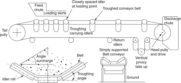
A complete belt conveyor comprises numerous components. Below, I have listed these components and will explain their functions and technical requirements in detail one by one. Understanding these components is fundamental to selecting the correct model and maintaining the equipment.
Part One: List of Components
A complete belt conveyor should include the following components (though this list is not exhaustive):
| No. | Component Name |
|---|---|
| 1 | Conveyor Belt |
| 2 | Idler Sets |
| 3 | Pulley Assemblies |
| 4 | Drive Unit (including electric motor, gearbox, coupling, base frame, etc.) |
| 5 | Disc Brake |
| 6 | Backstop (Non-reversing device) |
| 7 | Take-up Unit (Tensioning device) |
| 8 | Loading Chute |
| 9 | Belt Cleaner (Scraper) |
| 10 | Steel Structures (stringer frame, support legs, pulley brackets, receiving plates, safety guards, handrails, etc.) |
| 11 | Coatings, Solvents, Oils, Lubricants (for on-site touch-up and trial operation) |
| 12 | Consumables and Wear Parts (for installation, commissioning, and trial operation) |
| 13 | Special Tools, Instruments, and Gauges (for installation, maintenance, inspection, and operation) |
Part Two: Conveyor Belts – The Core Traction and Load-bearing Components
The Function of Conveyor Belts
Conveyor belts are the primary components in belt conveyors responsible for traction and carrying materials. They must possess both sufficient strength and the appropriate load-bearing capacity.
Selection of Conveyor Belts
Depending on the required tension, the following types of conveyor belts may be selected:
Flame-retardant, anti-static, solid-core PVG conveyor belts: Specifications range from PVG680S to PVG2500S
Flame-retardant, anti-static, solid-core PVC conveyor belts: Specifications range from PVC680S to PVC2500S
Flame-retardant steel-cord belts: Specifications range from ST/S630 to ST/S4000 N/mm
Applicable standard: MT 668-1997
Conveyor belt splicing
Conveyor belts should generally be spliced using vulcanisation. Specific requirements are as follows:
The static strength retention at the vulcanised joint must not be less than 100%
The service life is generally not less than 10 years
The sum of permanent elongation and elastic elongation shall not exceed 0.2%
Supplier’s Responsibilities
The conveyor belt manufacturer shall provide the following:
Splicing methods
Compounds for splicing
Requirements for the environment surrounding the splice
Requirements for the vulcanising equipment
Technical training for the user’s splicing personnel
And shall be responsible for the efficiency of the splicing
Part Three: Drive Unit – The Core of Power Supply
Composition of the Drive Unit
The drive unit comprises the following components:
Motor
Gearbox
Hydraulic soft-start device
Brake
Backstop
High-speed shaft coupling
Low-speed shaft coupling
The entire drive unit is mounted on a drive frame, which is in turn secured to the foundation.
Requirements for the motor
A mining-grade explosion-proof three-phase induction motor shall be used. It must be capable of trouble-free operation under the following conditions:
Full-load operation
Voltage variations within ±5% of the rated voltage
Frequency variations within ±1% of the rated frequency
Characteristics of the Reducer
The reducer should possess the following advantages:
High load-bearing capacity
High efficiency
Light weight
Long service life
Coupling Requirements
The coupling utilises serpentine springs as its elastic elements. It should meet the following conditions:
| Requirement | Description |
|---|---|
| Good Elasticity | Strong impact resistance and cushioning / shock absorption capacity |
| Rated Capacity | Not less than 1.5 times the transmitted torque |
| Compensation Capability | Good compensation capability in axial, radial, and angular directions |
| Easy Maintenance | Installation and disassembly without moving the motor or driven machine |
| Long Service Life | Long maintenance intervals |
Requirements for the drive unit frame
The drive unit frame is a welded steel plate structure and must meet the following requirements:
The surfaces in contact with the reducer and motor base must be machined
A set of shims is provided beneath the motor base
A screw adjuster is fitted on each side of the motor
It must possess sufficient rigidity, strength and stability
Anchor bolts must be securely fastened, with no abnormal vibration
Steel Pre-treatment Requirements:
High-quality steel must be selected
Shot blasting pre-treatment shall be used to remove mill scale, rust and foreign matter
Rust removal grade: Sa2½
A pre-treatment primer shall be applied
High stresses caused by welding or machining shall be relieved
Part Four: Rollers – Power Transmission Components
Classification of Rollers
Rollers are classified into two types: drive rollers and idler rollers. They are the primary power transmission components of belt conveyors and are fabricated by welding the shell and flanges together.
Manufacturing Methods:
Outer diameter ≤ 320 mm: Seamless steel tubes are used for the shell
Outer diameter > 320 mm: Steel plates are rolled and butt-welded (known as welded drums)
Cast steel flanges are welded to the drum shell (known as cast-welded structure drums)
Drive Drums
Drive drums are the primary components for transmitting power. They can be classified by arrangement as follows:
Single drum (cover angle 210°–230°)
Twin-drum (covering angle up to 350°)
Multi-drum (used for high power)
By surface configuration, they can be classified as:
| Pulley Type | Advantages | Disadvantages | Applicable Applications |
|---|---|---|---|
| Steel Smooth Pulley | Simple manufacturing | Low friction coefficient | Short-distance conveyors |
| Rubber Lagged Pulley | High friction coefficient | Complex manufacturing process | Long-distance, large-capacity conveyors |
| Ceramic Lagged Pulley | High friction coefficient | High cost | Long-distance, large-capacity conveyors |
Surface profiles of rubber-covered rollers:
Smooth rubber covering: Standard type
Diamond (checkered) pattern rubber covering: Used for conveyors operating in both directions
Herringbone groove rubber covering: High coefficient of friction, good slip resistance and drainage, but directional requirements apply
Redirecting rollers
The function of redirecting rollers is:
To change the direction of the conveyor belt
To increase the wrap angle of the conveyor belt around the drive roller
Deflection rollers feature a smooth rubber surface.
Requirements for the roller shaft
Must be a forged component
Must undergo non-destructive testing, with a test report provided
The permissible torque and permissible resultant force must meet design requirements
Part Five: Idlers – Support Components
The function of idlers
Idlers are used to support the conveyor belt and the material it carries, ensuring the stable operation of the conveyor belt.
Types of idlers
| Idler Type | Installation Position | Function |
|---|---|---|
| Trough Idler Set | Carrying side (upper branch) | Supports the material and the conveyor belt |
| Transition Idler Set | Near pulleys | Provides transition with trough angle from 5° to 30° |
| Self-Aligning Idler Set | Carrying side or return side | Prevents belt misalignment and centers the belt |
| Impact Idler Set | Below the chute at the loading point | Absorbs impact energy |
| V-Return Idler Set | Return branch | Centers the empty conveyor belt |
| Flat Return Idler | Return branch | Supports the return belt |
Roller spacing
| Position | Spacing |
|---|---|
| Carrying side (upper branch) | 1000–1200 mm |
| Return side (lower branch) | 2400–3000 mm |
| Convex / concave curve section | 500 or 600 mm (determined by calculation) |
| Impact idlers | 1/2 to 1/3 of trough idler spacing |
Quality specifications for assembled rollers
| Parameter | Requirement |
|---|---|
| Simulated friction coefficient (fully loaded) | f ≤ 0.020 |
| Service life | 30,000 hours (excluding impact idlers), failure rate ≤ 3% |
| Rotational resistance | ≤ 3.0 N (radial load 250 N, speed 550 r/min); ≤ 1.5 times after 1 hour of stoppage |
| Radial runout | ≤ 0.5 mm (excluding impact idlers) |
| Axial displacement | ≤ 0.7 mm (under 500 N axial force) |
| Dust resistance | After 200 hours of operation in a coal dust container, no coal dust shall enter the bearing grease |
| Water resistance | After 72 hours of operation under water spray, water ingress ≤ 150 g |
| Axial load capacity | 15 kN |
| Drop test | No damage, no cracks |
Part Six: Tensioning Device
Function of the Tensioning Device
The functions of the tensioning device are:
To ensure that the conveyor belt does not slip on the drive drum
To limit the sag of the conveyor belt between the idler groups
To provide the necessary travel for splicing the conveyor belt
Types of Tensioning Devices
Common types include:
Screw type
Winch type
Vertical type
Hydraulic tensioning
Tensioning winch
Part Seven: Frame
Function and Structure of the Frame
The frame constitutes the main structural framework of the belt conveyor. It features a triangular structure welded from H-section steel. The surfaces connecting to the drums must be machined. Welded components in the main tension-bearing members should undergo non-destructive testing.
Types of Frame
| Type | Application |
|---|---|
| 01 Frame | Discharge pulley frame |
| 02 Frame | Drive pulley frame / Bend pulley frame |
| 03 Frame | Bend pulley frame / Tail pulley frame |
Intermediate support
Standard type: 6 m long, with roller mounting hole spacing of 1000 mm or 1200 mm
Non-standard type: Less than 6 m, hole spacing to be drilled on site
Convex curve section: Curvature radii 12, 16, 20, 24, 28, 34 m (6 types in total)
Concave curve section: Curvature radii 80 m, 120 m, 150 m
Intermediate support legs
| Type | Feature |
|---|---|
| Type I | Without diagonal brace |
| Type II | With diagonal brace |
The support legs and intermediate frames are bolted together for ease of transport.
Part Eight: Guide Chute
The purpose of the guide chute is to direct material falling from the hopper towards the centre of the conveyor belt.
Base width: 1/2 to 2/3 of the belt width
Cross-sectional shape: Rectangular
Components: front section, middle section, rear section (lengths to be determined according to customer requirements)
Part Nine: Cleaner
The cleaner is used to remove material adhering to the conveyor belt.
| Type | Function |
|---|---|
| Scraper-style belt cleaner | Simplest basic type |
| P-type / H-type alloy belt cleaner | High-efficiency cleaning; install according to the instruction manual |
| Empty-run (return side) belt cleaner | Removes material adhered to the non-carrying side of the belt |
Part Ten: Safety Protection
Safety Guardrails and Safety Nets
Safety guardrails and safety nets must be installed on exposed parts of mechanical drive systems:
Safety nets must be installed on the side adjacent to overhead passenger conveyors to prevent materials from flying out and causing injury.
Safety guards must be fitted to drive drums and deflection drums.
Safety guardrails shall be installed around the tensioning device;
Safety guardrails or safety guards shall be installed on other rotating or moving parts;
Safety guards are generally made of galvanised diamond mesh for ease of assembly, disassembly and handling.
Data sources:
MT 668-1997 ‘Flame-retardant steel-cord conveyor belts for coal mines’
GB/T 10595-2017 “Belt Conveyors”
MT/T 821-2006 “Technical Specifications for Idlers of Belt Conveyors for Coal Mines”
The quality indicators for idlers mentioned in the text (rotational resistance, radial runout, axial displacement, dust and water resistance tests, etc.) refer to MT/T 821-2006
Data on frame curvature radius is based on industry design manuals and GB/T 10595-2017
Surface rust removal grade Sa2 1/2 is based on ISO 8501-1 “Rust and cleaning grades for steel surfaces prior to painting”
 English
 العربية
 Русский
 Español
 Português do Brasil