
Best Guide to Tail Pulley Function in Belt Conveyors
A belt conveyor might look like a simple piece of industrial machinery, but its mechanical structure relies on several highly specialized components working in sync. When looking at a conveyor in a factory or mine, naming each structural part accurately can be tricky.
Here is a clear, step-by-step technical breakdown of the core components that make up a industrial belt conveyor system.
1. Conveyor Belting Materials and Working Environment
The conveyor belt is the main load-carrying surface. Selecting the right belt matrix depends directly on working temperatures, material characteristics, and mechanical stress.
- Rubber Conveyor Belts: Standard rubber belting performs best in ambient working temperatures ranging from -15°C to 40°C. They offer resistance against abrasion, oils, acids, and cold weather. For materials exceeding 50°C, high-temperature heat-resistant belting must be specified.
- Steel-Cord Conveyor Belts: Engineered with longitudinal steel cables, these belts provide high tensile strength and minimal elongation. They handle long distances and heavy-duty bulk transport with smooth startup mechanics.
- Nylon and Canvas Belts: Constructed with synthetic carcass layers, these belts offer excellent elasticity and troughing capabilities. Coated with chemical-resistant covers, they are widely used in fertilizer, paper, and chemical processing plants.
| Belt Type | Core Material | Key Strengths | Suitable Applications |
| Rubber Cover | Synthetic/Natural Rubber | Abrasion & Chemical Resistance | Mining, Aggregates (-15°C to 40°C) |
| Steel-Cord | High-Tensile Steel Cables | High Strength, Low Elongation | Long-Distance Bulk Handling |
| Nylon/Canvas | Multi-ply Fabric Carcass | Excellent Troughing & Elasticity | Chemical & Paper Plants |
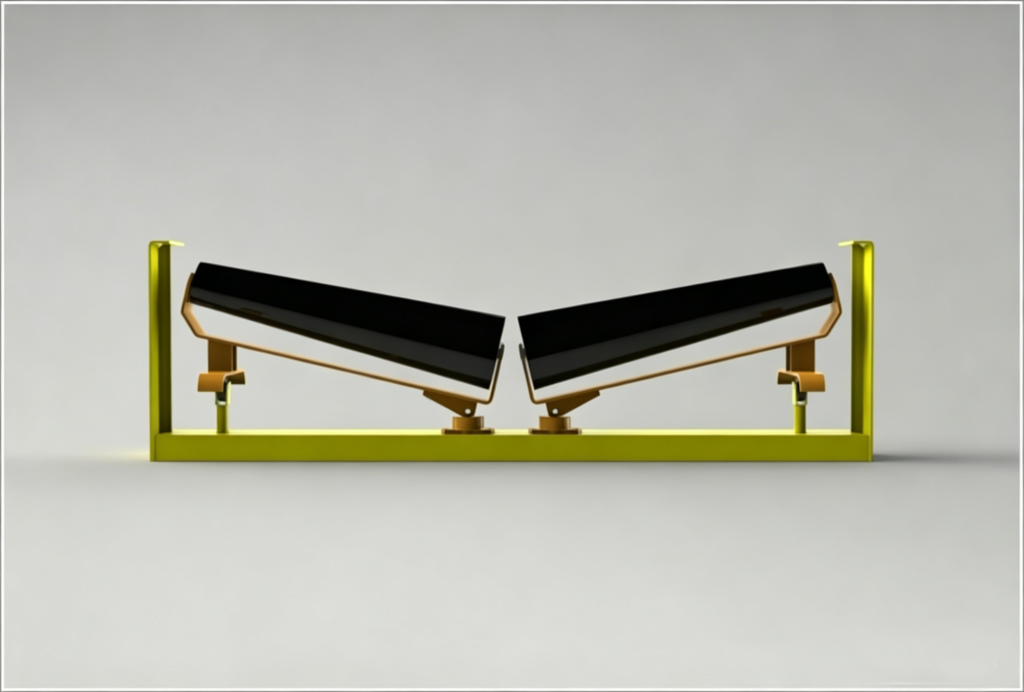
2. Idler Sets and Support Rollers
Idlers support the belt and the bulk payload along the conveyor frame, maintaining proper belt shape and tracking.
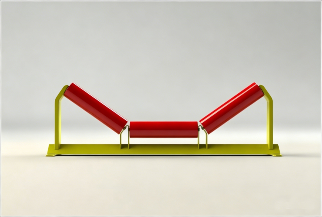
- Troughing Idlers: Made of a three-roller set that shapes the belt into a trough to maximize bulk material volume.
- Self-Aligning Idlers: Automatically correct lateral belt drift (off-tracking) to prevent edge wear.
- Impact Idlers: Installed directly beneath the loading chute, featuring shock-absorbing rubber rings to cushion material impact.
- Flat Return Idlers: Support the empty belt as it travels back along the bottom side of the conveyor frame.
3. Drive Pulley and Tail Pulley Assemblies
Pulleys transmit mechanical torque and redirect the belt direction.
- Drive Pulley: Connects directly to the electric motor and gearbox assembly to supply traction. Common light-duty diameter standards include 38.1 mm, 50.8 mm, and 60 mm, while heavy-duty systems use larger fabricated steel drums.
- Tail (Bend) Pulley: Positioned at the loading or tail end of the conveyor to redirect belt direction. Small units utilize cast iron construction, while larger industrial systems use welded steel plate construction.
4. Tensioning Devices
Tensioners keep the belt taut to prevent slippage across the drive pulley face and limit sag between idler sets.
- Screw Tensioners: Manual threaded adjustment used primarily on short, light-duty conveyors.
- Gravity Take-Up Units: Uses a counterweight box on a vertical frame to provide continuous tensioning over long distances.
- Winch and Trolley Take-Up: Mechanical winches pull a tensioning trolley along a track for long-distance, high-capacity systems.
5. Belt Cleaners and Scrapers
Cleaners remove residual material sticking to the return belt and rollers, avoiding carryback buildup.
- Primary Scrapers: Polyurethane (PUR) blades mounted on the head pulley just below the discharge trajectory.
- Secondary Scrapers: Alloy-tipped blades placed along the flat return path for fine cleaning.
- V-Plow Cleaners: Mounted inside the return belt loop in front of the tail pulley to remove fugitive material.
6. Motor Power and Engineering Calculation
The drive motor acts as the core powertrain. Sizing requires precise engineering calculations based on belt width, length, incline angle, throughput, and material friction.
Per the ISO 5048 / DIN 22101 standards for continuous mechanical handling equipment, the required drive power ($P$) at the motor shaft is calculated using total effective pull ($F_U$) and belt speed ($v$):
$$P = \frac{F_U \cdot v}{1000 \cdot \eta}$$
Where:
- $P$ = Required motor power ($\text{kW}$)
- $F_U$ = Total effective peripheral drive force ($\text{N}$)
- $v$ = Belt speed ($\text{m/s}$)
- $\eta$ = Mechanical drive efficiency (typically $0.85 – 0.92$)
The effective peripheral force $F_U$ accounts for main resistance ($F_M$), secondary resistance ($F_S$), and lift resistance ($F_{St}$):
$$F_U = f \cdot L \cdot g \cdot \left[ q_B + q_R + (2 \cdot q_G + q_B) \cdot \cos(\delta) \right] + (q_G \cdot g \cdot H)$$
Where:
- $f$ = Artificial friction factor (typically $0.020 – 0.030$)
- $L$ = Conveyor center-to-center length ($\text{m}$)
- $g$ = Acceleration due to gravity ($9.81\ \text{m/s}^2$)
- $q_B$ = Belt mass per meter ($\text{kg/m}$)
- $q_R$ = Rotating mass of idlers per meter ($\text{kg/m}$)
- $q_G$ = Material load per meter ($\text{kg/m}$)
- $\delta$ = Incline angle ($\text{degrees}$)
- $H$ = Vertical lift height ($\text{m}$)
Engineering References
- DIN 22101:2011-12 — Continuous conveyors – Belt conveyors for loose bulk materials – Basics for calculation and dimensioning. Deutsches Institut für Normung.
- ISO 5048:1989 — Continuous mechanical handling equipment — Belt conveyors with carrying idlers — Calculation of operating power and tensile forces. International Organization for Standardization.
- CEMA (Conveyor Equipment Manufacturers Association) — Belt Conveyors for Bulk Materials, 7th Edition.

 English
 العربية
 Русский
 Español
 Português do Brasil