
Steel Plant Dust Collector Retrofit: Engineering Design Guide
- Project Overview and Weather Challenges
- Thermal Expansion and Structural Precision Control
- Construction Sequencing and Anti-Corrosion Adjustments
- Electrical Insulation and Wet Weather Management
- Parallel and Cross-Operational Project Management
- Current Project Status and Technical Outlook
- References and Standards
Project Overview and Weather Challenges
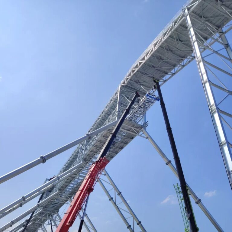
During the summer, the middle and lower reaches of the Yangtze River experience extreme weather characterized by a combination of high atmospheric temperatures and high relative humidity (the regional “plum rain” season). This environment presents severe physical and mechanical challenges to industrial installation projects.
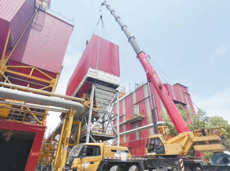
This technical report details the construction strategies and engineering solutions implemented by Haihui Environmental Protection Equipment Co., Ltd. (海汇环保设备公司) during a critical desulfurization dust collector retrofit project at a major steel plant. As a key environmental upgrade, this project directly impacts emissions compliance and the operational stability of the plant’s production units.
Thermal Expansion and Structural Precision Control
In July, ambient ground temperatures at the outdoor construction site consistently exceeded $38^\circ\text{C}$. The metallic shells of the dust collector components absorb solar radiation, reaching surface temperatures far higher than the surrounding air. This thermal energy causes significant linear expansion in large steel structures. If structural alignment and bolting are performed during peak heat hours, the steel contracts as it cools down, causing structural misalignment, joint stress, and seal failures.
To calculate and offset these thermal variations, engineering teams utilized the standard linear thermal expansion relationship:
$$\Delta L = L \cdot \alpha \cdot (T_{surface} – T_{install})$$
Where:
- $\Delta L$ = Dimensional variation of the steel component ($\text{mm}$)
- $L$ = Nominal structural length of the component ($\text{mm}$)
- $\alpha$ = Coefficient of linear thermal expansion for structural carbon steel ($1.2 \times 10^{-5} \text{ / } ^\circ\text{C}$ [16])
- $T_{surface}$ = Surface temperature of the steel during peak sunlight hours ($^\circ\text{C}$)
- $T_{install}$ = Calibration target installation temperature ($^\circ\text{C}$, typically standardized to a reference of $20^\circ\text{C}$)
For instance, a structural beam segment of $15\text{ m}$ ($15000\text{ mm}$) exposed to direct sunlight can easily reach a surface temperature of $55^\circ\text{C}$. The resulting structural deviation is calculated as follows:
$$\Delta L = 15000 \cdot (1.2 \times 10^{-5}) \cdot (55 – 20) = 6.3\text{ mm}$$
A deviation of $6.3\text{ mm}$ exceeds the allowable tolerance limits for high-performance gas seals in desulfurization systems.
[Peak Heat Hours: Structural Expansion] ──> Deviations up to 6.3 mm
                                                     │
                                                     ▼ (Corrective Action)
[Shift Precision Calibration to Cool Hours] ──> Deviations restricted below 1.0 mm
Construction Sequencing and Anti-Corrosion Adjustments
To eliminate thermal deformation errors, the project department adjusted the scheduling of high-precision tasks. Structural calibration, leveling, and final joint sealing were moved to early morning and late evening hours when surface temperatures stabilized near the reference baseline. Field crews used industrial laser levels to continuously verify alignment, successfully restricting final assembly deviations to under $1.0\text{ mm}$.
Additionally, high humidity during the rainy season accelerates oxidation on freshly prepared weld joints. To prevent moisture-induced corrosion, the following protocol was established:
- Immediate Coating: An anti-corrosive, moisture-resistant protective primer was applied to weld seams immediately after slag removal and non-destructive testing (NDT).
- Protective Wrapping: Temporary heavy-duty plastic sheeting was wrapped around uncompleted joint connections to isolate the bare metal from ambient moisture.
Electrical Insulation and Wet Weather Management
High relative humidity combined with sudden rainstorms poses severe risks to electrical systems. Moisture ingress lowers the insulation resistance of electrical cables, control instruments, and motor windings, which can lead to short circuits, equipment failure, or electrical hazards.
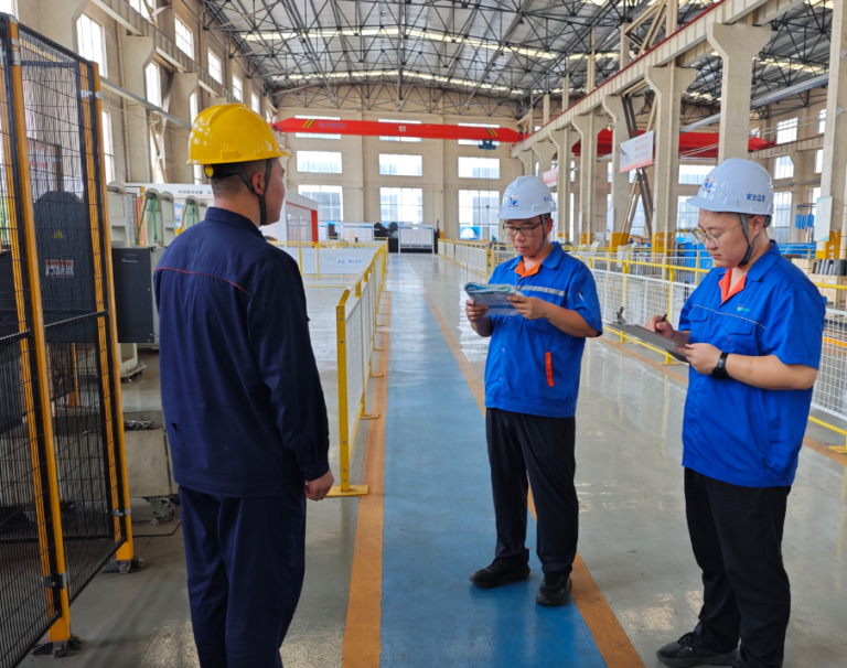
To ensure safety, electricians measured insulation values before energizing any circuit. The table below outlines the minimum acceptable insulation resistance values required for the project under various system voltage ratings:
| Equipment Category | Rated System Voltage | Minimum Insulation Resistance | Testing Instrument Required |
| Low-Voltage Control Wiring | $< 100\text{ V}$ | $\ge 0.5\text{ M}\Omega$ [17] | $250\text{ V}$ Insulation Tester |
| Auxiliary Power Circuits | $380\text{ V}$ to $660\text{ V}$ | $\ge 1.0\text{ M}\Omega$ [17] | $500\text{ V}$ Megohmmeter |
| Heavy-Duty Fan Motors | $6\text{ kV}$ to $10\text{ kV}$ | $\ge 6.0\text{ M}\Omega$ [17] | $2500\text{ V}$ Megohmmeter |
To manage unpredictable rainstorms, the project team implemented a rapid-response system:
- Weatherproof Covers: Custom waterproof tarpaulins were pre-installed over open-air motors and terminal connection boxes.
- Mandatory Testing: After every rainfall event, field engineers used megohmmeters to verify insulation resistance across all exposed circuits before resuming work.
Parallel and Cross-Operational Project Management
To make up for weather-related delays, the project department abandoned traditional sequential workflows in favor of a synchronized, multi-point parallel construction model.
[Traditional Sequential Model]
Stage 1: Mechanical Assembly ──> Stage 2: Electrical Installation (Total: 21 Days)

[Parallel Integration Model]
Zone A: Mechanical + Electrical Parallel Work ──┐
Zone B: Mechanical + Electrical Parallel Work ──┼──> Integrated Final Commissioning (Total: 14 Days)
Zone C: Mechanical + Electrical Parallel Work ──┘
The construction site was divided into distinct structural zones. The mechanical installation crews and electrical teams worked simultaneously within the same zones. Using real-time radio communication and structured daily schedules, the teams coordinated task handovers hour-by-hour. This parallel integration allowed electrical conduits to be run while mechanical seals were curing, saving approximately 7 days compared to the original project timeline.
Current Project Status and Technical Outlook
The main structural assembly of the desulfurization dust collector is now securely positioned, and the alignment of the key inlet and outlet ducts is complete. The installation of auxiliary electrical wiring, power distribution cabinets, and control sensors is proceeding on schedule.
By applying rigorous thermal calculations, proactive moisture controls, and collaborative scheduling, the engineering team maintained high quality and safety standards despite severe environmental conditions. This project serves as a model for executing heavy industrial retrofits during extreme summer weather.
References and Standards
- [16] ASTM A36/A36M Standard Specification for Carbon Structural Steel, Thermal Properties and Expansion Coefficients Database.
- [17] National Electrical Code (NEC) / NFPA 70, Standard Testing Procedures and Minimum Insulation Resistance for Industrial Rotating Machinery and Control Circuits.
 English
 العربية
 Русский
 Español
 Português do Brasil